Vehicles
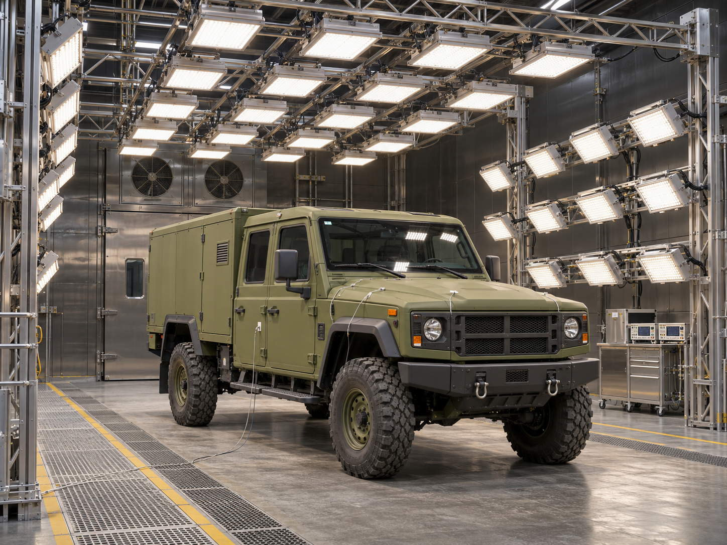
Solar Simulation for Military Vehicles
Military vehicles can be exposed to direct solar radiation for extended periods. Roofs, side surfaces and glazing heat up as a result. This external load influences the vehicle’s temperature conditions and the conditions inside enclosed passenger and equipment compartments.
A suitably designed solar simulation system makes it possible to investigate these relationships independently of changing weather conditions. Depending on the test objective, individual components, vehicle areas or complete vehicles are examined.
BF Engineering develops large-area irradiation systems for these test environments. Vehicle geometry, relevant irradiation surfaces and integration with existing climatic and measurement equipment form the basis of the design.
Consider the vehicle as a complete thermal system
Temperature development in a vehicle results from the interaction of radiation absorption, heat transfer and heat dissipation. Investigations of the complete vehicle can show how external loading affects different areas.
For comparative tests, the vehicle configuration and initial conditions are clearly defined. These include, for example, the position of doors and covers and the state of existing ventilation or air conditioning systems. This allows different configurations to be compared under traceable conditions.
Typical areas of investigation:
- Heating of the roof, side surfaces and glazing
- Temperature development in passenger and equipment compartments
- Comparison of different insulation and surface configurations
- Behaviour under specified ventilation and air conditioning states
- Heating and cooling profiles over defined test phases
Coordinate irradiation surfaces with the vehicle contour
The arrangement of the radiation sources is based on the vehicle’s dimensions and geometry. The surfaces to be exposed and the irradiation directions are defined accordingly.
Superstructures, attached components and surfaces at different angles can change the radiation distribution. Planning therefore considers both suitable reference surfaces and the actual vehicle contour. Required vehicle variants are considered when defining the usable test area.
Key design parameters:
- Vehicle dimensions and intended test positions
- Size and position of the irradiation surfaces
- Irradiance and spatial distribution
- Irradiation direction and luminaire distance
- Shading caused by superstructures and attached components
Investigate heat input and local temperature differences
The effects of external irradiation on the interior can be delayed. Different wall constructions, glazing and interior fittings influence how temperatures develop and are distributed.
Measurement planning therefore includes several relevant areas. Depending on the investigation, occupied zones, storage spaces or enclosed equipment compartments can be examined. Additional internal heat loads are included only if they are specified and clearly described in the test concept.
Possible areas of investigation:
- Air temperatures in selected interior areas
- Surface temperatures on interior panels
- Temperature differences between individual zones
- Influence of glazing and sun protection
- Effects of defined internal heat loads
Correlate loading and vehicle response over time
For a traceable evaluation, irradiation conditions are recorded together with measurement data from the vehicle. Reference positions allow the radiation load to be checked, while additional sensors capture the thermal response.
Alongside individual temperatures, their development over the test period is relevant. Changes to the vehicle state, interventions during the experiment and interruptions are therefore documented. Repeatable vehicle positions facilitate subsequent comparative tests.
Important measurement and documentation parameters:
- Irradiance on agreed reference surfaces
- External and internal temperatures at defined measurement points
- Ambient temperature and humidity, where applicable
- State of ventilation, air conditioning and internal loads
- Profiles over time and documented changes in the test sequence
Incorporate irradiation into the complete test environment
The system is coordinated with chamber geometry, vehicle access and test facility controls. Alongside the vehicle contour, clearances for instrumentation, access and maintenance are considered.
For projects involving standards, the specific requirements are derived from the agreed test plan. MIL-STD-810 provides for the selection of test methods and loads tailored to the intended environmental conditions; using an irradiation system alone therefore does not establish overall compliance with the standard.
Relevant integration considerations:
- Installation space, vehicle access and test position
- Electrical supply and additional heat release
- Coordination with climatic and ventilation equipment
- Control interfaces and test sequence
- Accessibility for maintenance and verification measurements
Any questions?
We're happy to help.
BF is a forward-looking company that specializes in the development, manufacture, and optimization of high-precision systems and specialized irradiation equipment for test benches.

Your contact person
Danelis Diaz
Management Backoffice

Never miss a thing
BF is a forward-looking company that specializes in the development, manufacture, and optimization of high-precision lighting systems and specialized illumination systems for test benches.
