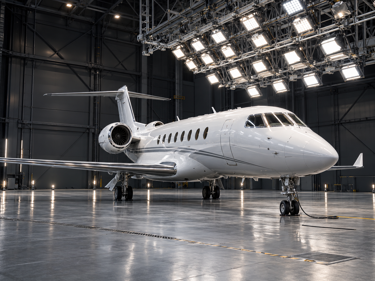
Solar Simulation for Aircraft
Investigating solar loads on the ground under defined conditions
Aircraft must cope with different thermal conditions even before take-off. During extended periods on the ground, solar radiation strikes the fuselage, glazing and exterior components. Surfaces heat up, heat is transferred to adjacent areas, and the initial conditions for subsequent operation change.
For development, it is therefore important to understand how individual materials, components and larger assemblies respond to this load. Solar simulation creates defined irradiation conditions for this purpose. Investigations can be planned and repeated under comparable boundary conditions.
Depending on the test objective, the focus is on thermal effects or light-induced changes in materials. Solar and UV irradiation tests are also used in the environmental testing of aerospace components.
Why controlled irradiation matters
During natural outdoor tests, the position of the sun, cloud cover and ambient conditions change. This makes direct comparisons between different components or development versions more difficult.
A suitably designed irradiation system makes it possible to investigate specific influences. Target areas, exposure duration and measurement conditions are defined in advance. This allows developers to assess, for example, the temperature differences between two surface finishes under identical test conditions.
The scope of the simulation depends on the task: component testing requires a different setup from the investigation of larger fuselage or glazing areas.
Customers who trust us
View all referencesInvestigating solar loads on materials, components and larger assemblies
Aircraft are exposed to different thermal influences even while on the ground. During extended periods of standstill, solar radiation strikes the fuselage, glazing and exterior components. The resulting heating depends on factors including surface material, coating, irradiation direction and ambient conditions.
Defined irradiation allows selected influences to be investigated systematically. The focus may be on how much a surface heats up, what temperatures occur behind glazing, or how an irradiated component responds during operation. Comparative tests support the evaluation of different materials and design variants.
The test is adapted to the desired outcome. Investigating short-term heating requires different test procedures from evaluating longer-term light-induced material changes. Solar and UV irradiation tests are also used in the environmental testing of aerospace components.
Typical areas of investigation:
- Temperature development on exterior skin, panels and housings
- Comparison of different surfaces and coatings
- Influence of glazing on the areas behind it
- Thermal behaviour of selected cockpit and cabin components
- Functional behaviour of irradiated electrical and electronic assemblies
- Comparison of different development versions under identical test conditions
Defining radiation characteristics to suit the development task
A suitable solar simulation system is designed around the test task. The required irradiance, spectrum, irradiation area and spatial distribution of radiation are decisive factors. The angle of incidence and the irradiation profile over time can also influence the results.
For thermal investigations, the amount of radiation energy absorbed by each surface is relevant. Different materials can respond differently to the same incident radiation. Irradiation should therefore always be considered together with the properties of the test object.
For light-induced material testing, the spectral composition is also particularly important. Temperature measurement alone does not fully describe this exposure.
System design also includes defining the reference area: irradiation values can only be interpreted clearly and subsequently reproduced when the measurement position, orientation and distance are specified.
Important design parameters:
- Irradiance across a defined reference area
- Spectral requirements of the test procedure
- Size and position of the area to be irradiated
- Direction of irradiation and distance from the test object
- Uniformity within the agreed measurement area
- Exposure duration and load profile over time
Adapting the luminaire arrangement and mechanical design to the aircraft geometry
Aircraft structures place particular demands on the spatial arrangement of an irradiation system. Curved fuselage surfaces, wings, the tail assembly and attached components influence which areas receive direct irradiation and where shading occurs.
System planning therefore begins by defining the relevant target areas. Will the investigation cover an individual component, a glazing area or a larger structure? The answer determines the requirements for luminaire positions, distances, the support structure and available installation space.
Handling the test object is also part of the system concept. Access, positioning and instrumentation must remain possible. Ongoing operation also requires access for maintenance, inspection and component replacement.
Depending on the application, a fixed or adjustable arrangement may be appropriate. Movement ranges and possible test positions are adapted to the geometry of the test object.
System design priorities:
- Alignment with the areas actually being investigated
- Consideration of the fuselage contour, wings and attached components
- Assessment of potential shading
- Defined and repeatable positioning of the test object
- Sufficient accessibility for instrumentation and servicing
- Coordination of the support structure, cable routing and installation space
Recording irradiation conditions and thermal response together
To evaluate a test, both the applied load and the response of the test object must be traceable. Irradiance describes the incident radiant power per unit area at a defined measurement position. Temperature measurements show how the component under investigation responds over time under these conditions.
Relevant measurement points, initial temperatures and operating states are defined before the test. Measurements that link irradiated surfaces with areas behind or adjacent to them are particularly informative. This allows heating and heat transfer to be investigated over time.
Depending on the task, contact sensors or non-contact measurement methods may be suitable. Non-contact temperature measurements must account for surface properties and possible reflections.
A consistent measurement arrangement is important for comparative tests. This includes documented positions, appropriate measurement intervals and a defined start to each load phase.
Relevant measurement and documentation parameters:
- Irradiance and, where applicable, spectral distribution
- Surface and component temperatures
- Ambient conditions during the test
- Operating state of the test object
- Heating and cooling profiles over time
- Positions and orientation of the measurement points
Incorporating irradiation into the existing test procedure
An irradiation system must fit the existing test environment both technically and operationally. In addition to the available installation space, planning considers the electrical supply, additional heat loads and intended operating procedures.
For operation, it must be established whether the system will run independently or be integrated into an overall test facility control system. This determines the requirements for setpoint commands, status signals, enable signals and the association of measurement data with the test procedure.
Safety functions and access to the test area must also be coordinated with the overall concept. Maintenance, bulb replacement and verification measurements should be considered during planning so that they remain practical during subsequent operation.
BF Engineering adapts the irradiation solution to the application and existing interfaces. Requirements are defined jointly with the operator and the participating test facility partners.
Relevant aspects of integration:
- Installation space, mounting positions and accessibility
- Electrical supply and additional heat input
- Operation and integration into test programmes
- Interfaces with the existing control system
- Safety functions and operational enable signals
- Maintenance procedures and recurring verification measurements
Any questions?
We're happy to help.
BF is a forward-looking company that specializes in the development, manufacture, and optimization of high-precision systems and specialized irradiation equipment for test benches.

Your contact person
Danelis Diaz
Management Backoffice

Never miss a thing
BF is a forward-looking company that specializes in the development, manufacture, and optimization of high-precision lighting systems and specialized illumination systems for test benches.
