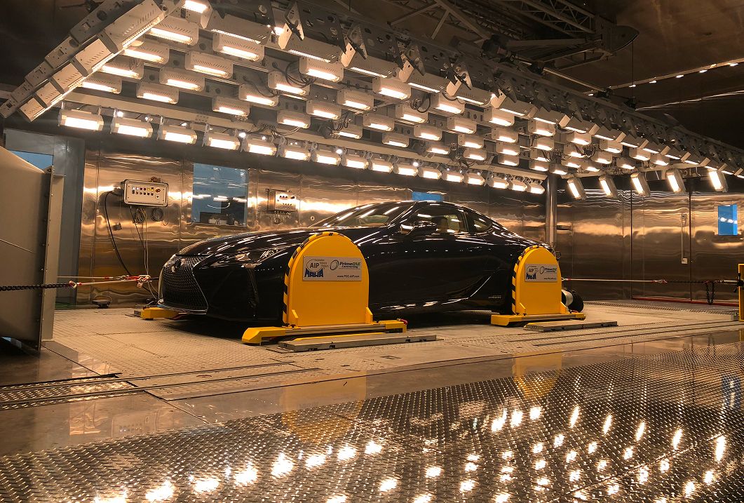
Emissions Test Stand (SC03)
Sun. Air Conditioning. Emissions. Under Defined Conditions.
A hot summer day in urban traffic: solar radiation heats the vehicle, the air conditioning is running, and changing driving conditions alter the load on the powertrain. This interaction affects energy demand and emissions behaviour.
The SC03 test procedure investigates gaseous exhaust emissions with the air conditioning switched on under specified environmental conditions. A defined solar load forms part of the test environment and represents an essential part of the thermal exposure.
BF Engineering develops and integrates solar simulation systems for these test tasks. The focus is on suitable irradiation geometry, a controllable radiation load and integration into the existing emissions test stand.
Why Solar Simulation Is Part of SC03 Testing
A high air temperature alone only partially describes the thermal load on a vehicle on a sunny day. Solar radiation strikes the bodywork and glazing, is reflected, transmitted or absorbed, and contributes to heating the interior.
The air conditioning system has to manage this heat load. Its operation requires energy and can affect the vehicle’s emissions behaviour. Research by the US National Renewable Energy Laboratory demonstrates the relationship between solar vehicle heating, air conditioning demand and additional energy consumption.
For comparable tests, the external conditions must therefore be set in a traceable manner. Solar simulation provides a defined radiation input that can be coordinated with the other test facility conditions.
The interaction between irradiation, climate control, vehicle airflow and a defined test procedure is crucial.
Investigating the vehicle under an additional thermal load
The SC03 test considers the emissions behaviour of the complete vehicle under defined driving and environmental conditions. Operation of the air conditioning system forms part of the test concept.
For development, it is important to understand how the powertrain, air conditioning and vehicle controls work together under this load. Solar simulation creates a specified external heat load for this purpose. It is therefore part of the test environment, while the exhaust measurement equipment records the emissions.
Additional development investigations can provide a deeper understanding of the thermal interactions. For example, interior temperature profiles or the effects of different vehicle configurations can be recorded. These additional measurements are adapted to the specific development question.
BF Engineering focuses on irradiation equipment and its integration. Coordination with the chassis dynamometer, climate control and exhaust measurement equipment takes place within the overall project.
Typical priorities:
- Defined solar load throughout the test procedure
- Interaction between vehicle air conditioning and powertrain operation
- Comparison of different development versions
- Additional recording of the vehicle’s thermal response
- Repeatable irradiation conditions for comparative tests
- Coordination of solar simulation with the complete test facility
Controlling several influencing factors together
A reproducible test requires more than a setpoint. The conditions must take effect at the vehicle and remain traceable throughout the relevant test phases.
These include the climatic conditions in the test cell, vehicle airflow and the solar load. A documented vehicle position and a clear association of the settings with the respective test are equally important.
The irradiation system is therefore designed in conjunction with the test cell. Its additional heat output must be considered during thermal planning. At the same time, luminaires, the support structure and cable routing must not unacceptably restrict the intended vehicle and service areas.
For operation, setpoints, verification measurements and enable conditions are coordinated. This makes it possible to determine whether the irradiation equipment is ready for the intended test phase and which settings were active during the test.
Important influencing factors:
- Test cell temperature and humidity
- Solar load at the vehicle
- Vehicle airflow and fan position
- Vehicle position within the irradiation area
- Sequence of test phases
- Documented system and vehicle settings
Providing the required radiation load at the vehicle
Solar simulation is adapted to the vehicle dimensions, the existing test cell and the intended measurement positions. The radiation that actually reaches the test object is decisive.
Luminaire arrangement, distance and alignment influence the distribution across the reference area. Planning therefore considers both the relevant vehicle measurement points and the irradiation distribution across the area. The corresponding criteria are shown separately in the technical specifications below.
Spectral properties are also considered during system design. The test procedure includes a recommended spectral distribution.
For test facility operation, it is also important that the required operating states can be set reliably. Warm-up behaviour, power control and verification measurements therefore form part of the system concept.
Important design parameters:
- Irradiance at the specified measurement positions
- Radiation distribution across the vehicle footprint
- Spectral properties of the radiation source
- Distance and alignment of the luminaires
- Coverage of the intended vehicle variants
- Stability during the relevant operating phases
Verifying irradiation quality in a traceable manner
The electrical power of the luminaires does not describe the irradiation conditions at the vehicle. These are checked using suitable radiation measurement equipment at defined positions.
Two tasks must be distinguished: checking the solar load at the specified vehicle measurement points and verifying the distribution across the area. Both measurements require defined geometry and traceable documentation.
The test procedure requires uniformity checks on a 0.5 m grid at a height of 1 m, covering the complete vehicle footprint, including its edges. The check must be performed at least every 500 hours of emitter operation or six months, whichever comes first, and after major modifications affecting the solar simulation.
For practical operation, measuring instruments, measurement positions and results should be clearly associated with one another. Additional temperature sensors can record the vehicle’s thermal response; they do not replace irradiance measurements.
Relevant measurement and documentation parameters:
- Irradiance values at the relevant vehicle measurement points
- Distribution across the specified measurement grid
- Position and orientation of the radiation sensors
- Measuring instruments used and their calibration status
- Luminaire configuration and operating state during measurement
- Results following maintenance or system modifications
Adapting irradiation equipment to the vehicle and test cell
The available installation space largely determines how solar simulation can be integrated into the emissions test stand. Vehicle height, wheelbase and body shape influence the required irradiation area and the possible distances from the luminaires.
The functions of the rest of the test facility must also be considered. These include vehicle airflow, positioning on the chassis dynamometer and access for measurement and service work.
The mechanical structure is planned around these conditions. Depending on the application, a fixed or adjustable luminaire arrangement may be appropriate. It is essential that the agreed test positions can be clearly defined and set repeatedly.
Maintenance and verification measurements also require sufficient space. Access to luminaires, filters and electrical components should therefore be considered during the concept phase.
System design priorities:
- Irradiation area suited to the intended vehicle portfolio
- Coordination of luminaire distance and vehicle height
- Consideration of the fan and vehicle airflow
- Accessibility of the chassis dynamometer and instrumentation
- Protected cable routing and suitable mountings
- Maintenance access and space for verification measurements
Operating solar simulation as part of the test facility
A solar simulation system must fit the technical and operational concept of the test cell. Supply systems, operation, interfaces and safety functions are therefore defined jointly with the operator.
For control, it must be established which commands come from the overall test facility and which feedback signals are required. These may include setpoints, readiness signals and fault messages. The desired functionality is defined for each project.
Coordination with the climate control system is equally important. The irradiation equipment introduces additional heat into the test cell. This influence must be considered during design and operation.
BF Engineering supports the design and integration of the irradiation solution. Requirements relating to the chassis dynamometer, exhaust measurement equipment and climate control are coordinated with the responsible system partners.
Relevant aspects of integration:
- Electrical supply and additional heat loads
- Interfaces with the test facility control system
- Setpoint commands and status signals
- Operating enable conditions and safety functions
- Timing in relation to the test phases
- Documentation, maintenance and recurring verification measurements
The following specifications refer to 40 CFR § 1066.835:
| Test parameter | Requirement |
|---|---|
| Solar load at the vehicle | 850 ± 45 W/m² |
| Determination of the solar load | Average of two measurements along the vehicle centreline: at the base of the windshield and at the bottom of the rear window, or at an equivalent alternative position |
| Irradiation distribution across the area | 722 to 978 W/m² at every point of the prescribed measurement grid |
| Temperature during the test sequence | 35.0 ± 3.0 °C |
| Average temperature during emissions sampling | 33.6 to 36.4 °C |
The checks at the vehicle measurement points and the area-wide uniformity test are separate verifications. The complete requirements for testing, measuring instruments and humidity are specified in the applicable procedure.
Any questions?
We're happy to help.
BF is a forward-looking company that specializes in the development, manufacture, and optimization of high-precision systems and specialized irradiation equipment for test benches.

Your contact person
Danelis Diaz
Management Backoffice

Never miss a thing
BF is a forward-looking company that specializes in the development, manufacture, and optimization of high-precision lighting systems and specialized illumination systems for test benches.
