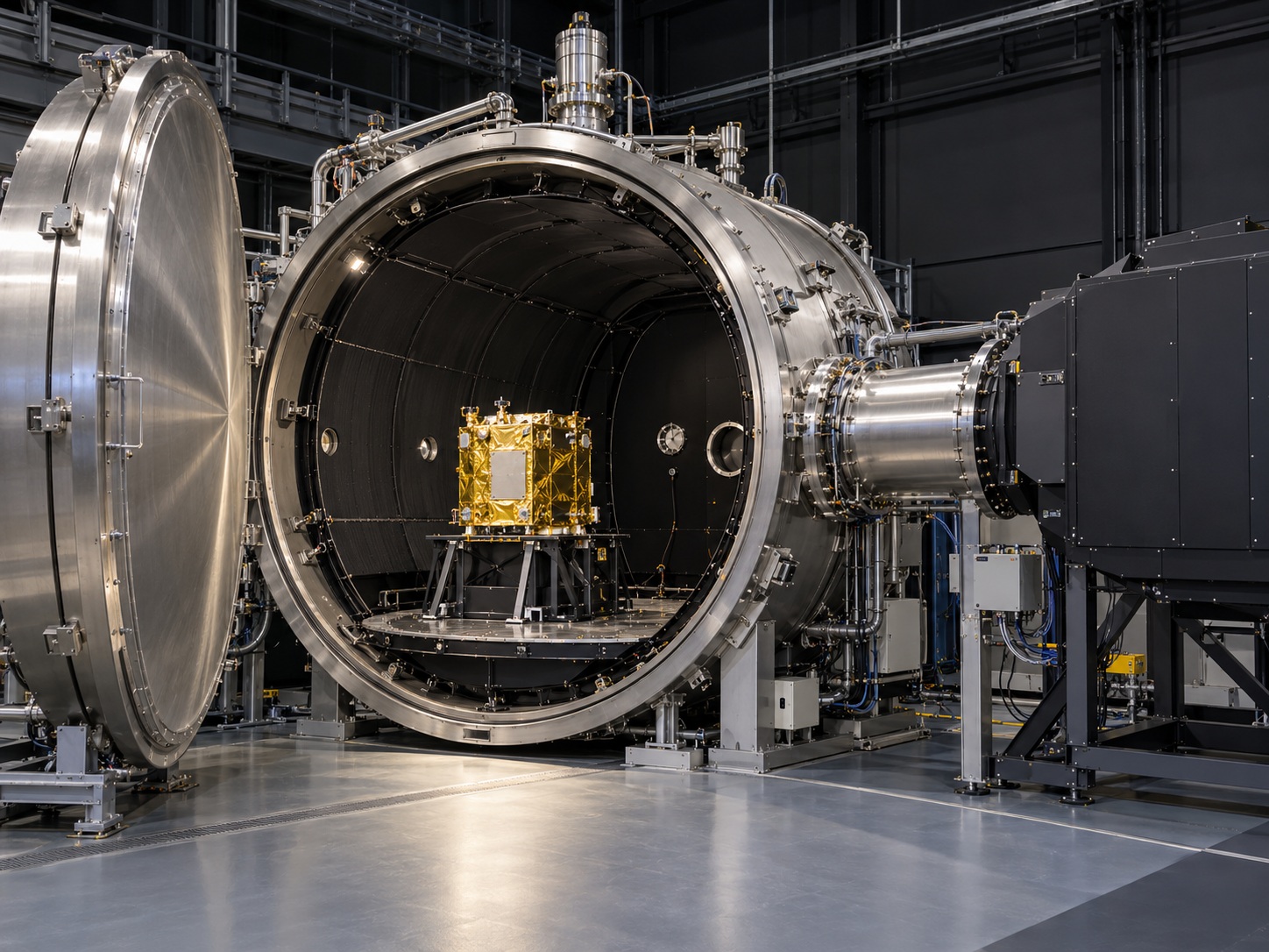
Solar Simulation in Vacuum Chambers
Combining radiation and thermal boundary conditions under controlled conditions
Vacuum chambers provide a test environment with reduced ambient pressure. For thermal spacecraft testing, they are combined with additional systems: temperature-controlled internal surfaces, suitable test object supports, measurement equipment and, where required, defined irradiation.
The interaction between these components determines the conditions at the test object. Solar simulation introduces a targeted radiation load, while temperature-controlled internal surfaces influence radiative heat exchange with the surroundings.
These facilities are used to investigate the thermal design of spacecraft components and systems and to verify calculation models using measurement data. Corresponding test concepts are documented by organisations including ESA and DLR.
Why Vacuum Changes the Thermal Balance
Under vacuum conditions, heat transfer through convection in the surrounding air is eliminated. Heat conduction through mechanical connections and radiative heat exchange therefore become particularly important.
The temperature of the chamber’s internal surfaces, the mounting of the test object and the applied radiation jointly influence its temperature distribution. Meaningful testing therefore requires a coordinated overall thermal concept.
For irradiation, this means considering not only the light source but also the optical access and the conditions inside the chamber.
Combining thermal test conditions under reduced pressure
Thermal vacuum testing combines reduced-pressure conditions with a defined thermal environment. Solar simulation or other suitable heat sources can also be used to apply specific loads to the test object.
The parameters to be combined depend on the test objective. A thermal balance test investigates the heat balance and temperature distribution under specified boundary conditions. Thermal cycling tests focus on behaviour during defined hot and cold phases.
The functionality of the test object can also be checked at selected temperature conditions. This requires defining which assemblies are active and how their internal heat generation affects the test.
DLR describes these tests as supporting the development and qualification of thermal systems and the verification of numerical models.
Typical test objectives:
- Investigation of thermal equilibrium states
- Determination of spatial temperature distributions
- Functional tests at defined temperature plateaus
- Evaluation of behaviour during thermal cycles
- Investigation of components and integrated systems
- Correlation and further development of thermal calculation models
Coordinating the radiation source, optical access and test object
With external solar simulation, radiation is introduced into the chamber through a specially designed optical interface. Actual facilities use, for example, a suitable window or a connected optical chamber section.
System design considers more than the light source alone. The transmission properties of the optical interface also influence the radiation that actually reaches the test object. The spectrum and irradiance must therefore be evaluated at the intended reference position.
Further parameters include the usable beam area, the direction of irradiation and the angular distribution of the radiation. For three-dimensional test objects, these can result in different loads on individual surfaces.
Alternatively or additionally, suitable infrared irradiation can be provided to apply thermal loads. The choice depends on the boundary conditions required for the investigation.
Important design parameters:
- Spectrum and irradiance at the test object
- Dimensions and position of the usable irradiation field
- Optical properties of windows and interfaces
- Direction of irradiation and beam geometry
- Uniformity across the defined reference area
- Possible combination with additional thermal load systems
Understanding the thermal environment as part of the test
A thermal vacuum facility consists of several coordinated subsystems. These may include the vacuum-tight chamber, pumps, temperature-controlled internal surfaces, the test object support, irradiation equipment and instrumentation.
The temperature-controlled internal surfaces are often referred to as shrouds. They influence radiative heat exchange between the test object and its surroundings. Their temperature is therefore an essential boundary condition of the test.
Heat conduction paths through mountings and cables also have an effect. The position of the test object inside the chamber can likewise be relevant, for example in relation to the irradiation area or its view of temperature-controlled surrounding surfaces.
Chamber geometry, thermal conditioning and irradiation are therefore considered together during planning. A clearly documented configuration makes subsequent test repetition and evaluation easier.
System design priorities:
- Usable chamber space and test object position
- Arrangement and temperature control of the shrouds
- Optical access and irradiation geometry
- Thermal properties of the test object support
- Suitable electrical and measurement feedthroughs
- Accessibility for setup, inspection and maintenance
Documenting pressure, temperature and irradiation together
The evaluation of a thermal vacuum test requires a complete description of the boundary conditions. In addition to test object temperatures, relevant parameters include the pressure profile, the conditions of the temperature-controlled surfaces and the irradiation settings.
Measurement points are defined according to the test purpose. They should capture thermally important areas and enable comparison with the calculation model. Sensor positions and attachment methods must be documented.
The measurement arrangement itself can also influence the result. Sensor cables can conduct heat away from or towards components, while unsuitable attachments can alter thermal contact. These influences must be considered during instrumentation.
Non-contact measurements through optical interfaces must also account for the properties of the window and the selected measurement method. The measurement concept is therefore developed together with the chamber and irradiation setup.
Relevant measurement and documentation parameters:
- Temperatures at the test object and thermal interfaces
- Temperatures of the shrouds and, where applicable, the base plate
- Pressure profile during the test phases
- Irradiance and relevant spectral properties
- Operating states and internal heat generation of the test object
- Measurement point positions, sensor attachments and cable routing
Establishing clear interfaces between irradiation and chamber operation
The integration of irradiation equipment begins with an assessment of the existing chamber connections, installation space and operating conditions. For retrofits, it must be established which optical and mechanical interfaces can be used and which modifications are required.
The irradiation equipment must work in coordination with chamber operation. This includes alignment with evacuation, thermal conditioning and venting, as well as suitable enable conditions for the different operating states.
The power supply and heat removal of the irradiation equipment are also considered. Whether components are located outside or inside the chamber influences the requirements for materials, cables and the cooling concept.
BF Engineering coordinates the irradiation equipment with the operator and the responsible chamber and system partners. The aim is a technically coordinated setup with defined responsibilities and clearly documented operating procedures.
Relevant aspects of integration:
- Existing flanges, windows and mechanical connections
- Optical coupling and alignment with the test object
- Electrical supply and cable feedthroughs
- Coordination with vacuum and temperature-control systems
- Enable conditions, interlocks and safety functions
- Control interfaces and combined data acquisition
- Accessibility for maintenance and verification measurements
Any questions?
We're happy to help.
BF is a forward-looking company that specializes in the development, manufacture, and optimization of high-precision systems and specialized irradiation equipment for test benches.

Your contact person
Danelis Diaz
Management Backoffice

Never miss a thing
BF is a forward-looking company that specializes in the development, manufacture, and optimization of high-precision lighting systems and specialized illumination systems for test benches.
